Online GCODE Converter. Select files for conversion or drag and drop them to the upload area. Your files are securely protected and available only to you. All files are automatically deleted from our servers after 1 hour.
Ribbon: Output -> CAD to G-code
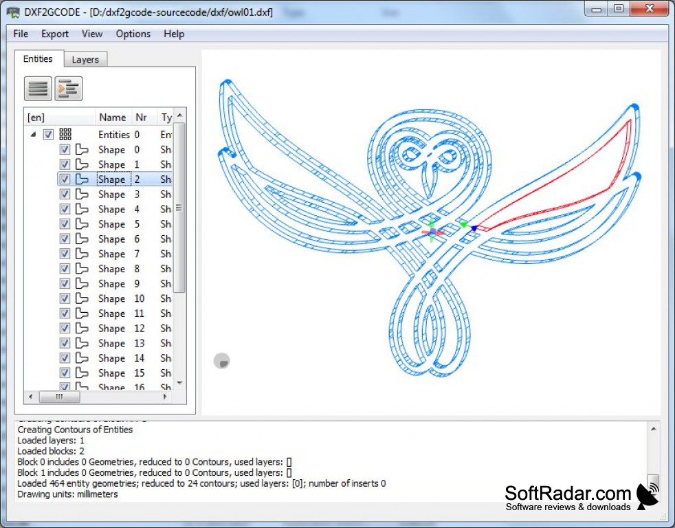
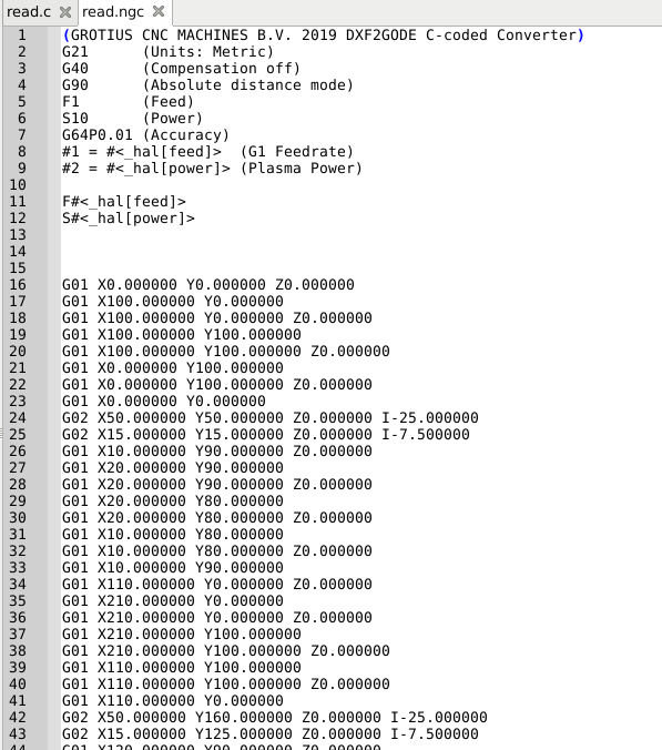
The program allows creating a control program (CP) in the G-code file format for CNC machines. G-code files are generated directly from DWG/DXF drawings. The following entities can be converted to G-code: lines, polylines, circles, arcs, ellipses, splines, texts, multiline texts and hatch.
- G-code Converter: How to Convert to and from G-code. By Hironori Kondo. Updated Jun 21, 2021. G-code is a vital part of the 3D printing workflow. Learn how to convert to and from this key format using a G-code converter or a slicer!
- Re: gcode to dxf converter. « Reply #1 on: January 06, 2007, 10:37:20 PM ». NCPLOT will convert gcode to dxf and save it, cant rember the format I think its Funuk code. It has a free 60 trial time, nice program, do a web search. Hope this Helps, Chip.
- Convert your DXF to G-Code with Scan2CAD. → Download your 14-day free trial. Scan2CAD makes it easy to directly export a vector image to G-Code. All you have to do is open up your DXF file in Scan2CAD and save it as G-Code. You have three options when it comes to the G-Code file extensions Scan2CAD supports:.CNC,.NC and.TAP.
To convert a file to G-code use the following instruction:
Stl To Gcode Converter

1.Open a DWG/DXF file and edit it if required.

2.On the Output tab in the Conversion group select the CAD to G-code command.

3.By default all drawing contours are converted. If you do not need to convert any particular contours, open the Processing queue window and uncheck them.
4.By default ABViewer generates a control program for a milling machine. To generate G-code for a laser machine select the required machine type in the G-code settings window on the General tab.
Free Gcode Converter
5.Click the Convert button. G-code will be generated automatically.
6.Click the Save G-code button. In the opened window enter the output file name and click Save. The file will be saved with the NC extension.
There is a toolbar under the G-code window name:
G-code settings. Opens the G-code settings window. |
Save G-code. Opens the window to save the *.nc file. |
Set a start point. Sets a new start point on the selected contour. To set a point, select a contour in the preview pane. The option is available only for closed contours. |
Processing queue. Enables to change the order of contour processing. |
Convert to G-code. Generates a control program from the drawing in the G-code format. |
Close G-code. Closes the G-code mode. |
Contour selection
You can indicate the sequence in which the contours will be processed in the Processing queue window. To change the contour position use the context menu. Only contours selected with a check mark in the contour list will be converted.
Preview pane
The opened drawing, the workpiece zero point, the start point of the tool movement, tool direction, the tool lead in/lead out method and the tool are displayed in the preview pane. The display of elements in the preview pane can be adjusted on the Color legend tab of the G-code settings window.
The user can select the required contour by clicking on it in the preview pane. The context menu is called with the right mouse button.
Properties
The tab includes additional tool settings: tool direction, lead in/lead out method, tool radius compensation. These settings are displayed in the preview pane.
Enable | Includes a contour in the G-code precessing list. |
Reverse contour | Changes tool direction from the start point along the selected contour. |
Shape type | Defines a contour type. |
Radius compensation | Tool radius compensation. The Off (G40) option discards tool radius compensation. The Leftward (G41) option compensates tool radius on the left of the trajectory. The Rightward (G42) option compensates tool radius on the right of the trajectory. |
Lead in | Sets the tool lead in method. The user can select one of the following lead in methods: tangent, normal, arc. Changes of the lead in method are displayed in the preview pane. To change the tool lead in direction tick the Reverse lead in checkbox. |
Reverse lead in | |
Lead out | Sets the tool lead out method. The user can select one of the following lead out methods: tangent, normal, arc. Changes of the tool lead out method are displayed in the preview pane. To change the tool lead out direction tick the Reverse lead out checkbox. |
Reverse lead out | |
Tool params | The drop-down list includes the tool and its parameters. The list is completed with the data from the Tools tab of the G-code settings window. |
G-code settings
The G-codesettings window includes the following tabs with settings: General, Milling machine, Laser (cutting) machine, Workpiece zero point, Tools, Color legend.
Color legend
Additional elements that will be displayed in the preview pane are selected by checking the corresponding element in the Color legend tab. To change the element color the user needs to click the corresponding color square. After it the standard Color window in which the user can select the required color will be opened.

Settings | Description | Code Example |
General | ||
Forward direction | The tool moves in the direction pointed by the arrow in the preview pane. | - |
Both directions alternately | At first the tool moves in the pointed direction and then backwards. | - |
Machine type | Sets the machine type: Milling/Cutting. | - |
Precision | Sets the number of digits after the decimal point. | - |
Drawing units | Sets drawing units. | - |
Machine units | Sets machine units are set. If units do not coincide, they are converted. | - |
Feed along XY | Speed of XY-direction cutting feed. If it is equal to 0, this value is ignored. | F450 |
Add block numbering | Adds numbering of blocks in the control program code. | N5 |
Starting number | Initial number of block numbering (default value: 5). | |
Step of numbering | Step of numbering. | |
Add program name | Adds program name to the control program code. | O001 |
Show comments | Shows commentaries in the control program code. | (Layout 'Model'), (Contour 0), (Contour 1) |
Show percent sign (%) | Adds the sign % to the control program code. | % |
Optimize code | Enables the code optimization - repetitive commands and coordinates are not duplicated. | - |
Milling machine | ||
Feed along Z | Speed of Z-direction cutting feed. | F150 |
Spindle speed | Rotation frequency of the spindle. | S3000 |
Feed depth along Z | Depth of penetration into a workpiece. | G1 Z-2 |
Retract height | Z-direction feed per one pass. The number of passes is calculated automatically. | M10 Q128/M11 |
Pass depth | Shifting of the tool from the workpiece in Z-direction. | G0 Z5 |
Laser (cutting) machine | ||
ON command | Command used to turn on the laser. Default value: M3. | M3 |
OFF command | Command used to turn off the laser. Default value: M5. | М5 |
Dwell (G4) | Delay of the program run. | G04 P100 |
Add power commands (M10, M11) | Turns on/off power commands. | M10 Q128/M11 |
Number of passes | The number of tool passes along the contour. | - |
Workpiece zero point | ||
Drawing zero point | Setting the workpiece zero point. | - |
Top left point | - | |
Top right point | - | |
Bottom left point | - | |
Bottom right point | - | |
Additional offset | Additional offset in X- and Y-directions. | - |
Tools | ||
No. | Number of the tool. | T1 M6 |
Diameter, mm | Diameter of the tool. | |
Length, mm | Length of the tool. |
| Name | STL | GCODE |
| Full name | Stereolithography File Format | G-Code 3D Printer File |
| File extension | .stl | .gcode |
| MIME type | ||
| Developed by | 3D Systems | Massachusetts Institute of Technology |
| Type of format | ||
| Description | STL is a file format native to the stereolithography CAD software created by 3D Systems. This file format is supported by many other software packages. It is widely used for rapid prototyping, 3D printing and computer-aided manufacturing. STL files describe only the surface geometry of a three-dimensional object without any representation of color, texture or other common CAD model attributes. The STL format specifies both ASCII and binary representations. Binary files are more common, since they are more compact. | A .GCODE file is created by a slicing program, which turns a CAD drawing into a string of code which a 3D printer can understand. G-code instructions are provided to a machine controller (industrial computer) that tells the motors where to move, how fast to move, and what path to follow. |
| Technical details | An STL file describes a raw, unstructured triangulated surface by the unit normal and vertices (ordered by the right-hand rule) of the triangles using a three-dimensional Cartesian coordinate system. In the original specification, all STL coordinates were required to be positive numbers, but this restriction is no longer enforced and negative coordinates are commonly encountered in STL files today. STL files contain no scale information, and the units are arbitrary. | |
| File conversion | STL conversion | GCODE conversion |
| Associated programs | TurboCAD, GOM Inspect, STL Viewer, Geomagic Explorer, Parametric Technology Creo, Dassault Systemes CATIA, KeyCreator, MeshLab, SolidWorks, Pro/Engineer, CloudCompare, Blender, AutoCAD, 3D Studio Max, Autodesk Inventor, Mechanical Desktop | Simplify3D, GCode Viewer, Blaze3D |
| Wiki | https://en.wikipedia.org/wiki/STL_(file_format) | https://en.wikipedia.org/wiki/G-code |